The main GUI of ExpEYES17 resembles a four channel oscilloscope, with additional elements for controlling the function generator, voltage source etc. The screen shot below shows data on three channels. Large number of activities can be performed using the scope GUI, shown below.
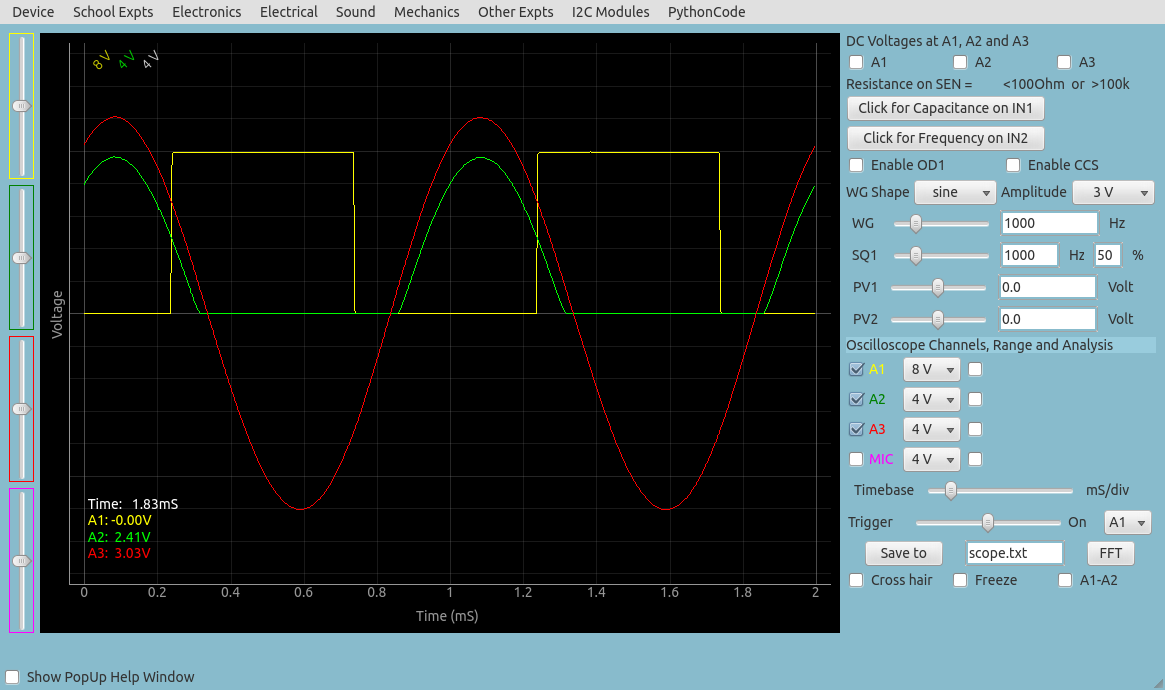
A brief description of the oscilloscope program is given below
- The Oscilloscope program mainly functions as a four channel DSO to view inputs A1, A2,A3 and MIC.
- Adjust the x-axis limit of the graph, using the Timebase Slider, generally to view several cycles of the waveform.
- If the waveform is not stable, select the proper trigger source. If needed adjust the Trigger level.
- The traces can be saved to a file, in text format. It is possible to take the Fourier transform and view the frequency spectrum of the input waveform.
- This scope program also has control/monitor widgets on the right side panel to access most of the ExpEYES features.
- The inputs A1, A2, A3 and the resistance connected to SEN are measured and displayed every second. But these readings are meaningless when AC inputs are connected.
- For sinusoidal AC inputs, enable the Check-Button in front of the channel widget to view the Peak voltage and frequency.
- The ExpEYES Input/Output terminals are briefly described below.

Output Terminals
- CCS: 1.1mA Constant Current Source. On/Off using Check-Button Enable CCS.
- PV1: Progrmmable Voltage, +/5 volts range. Can be set using the Slider or Text-Entry widget
- PV2: Similar to PV1, but ranges from -3.3V to +3.3V
- SQ1: Square Wave Generator, swings from 0 to 5V. Frequency can be set from 1Hz to 5kHz
- SQ2: Same as SQ1, but available as an option of WG.
- OD1: Digital Output, voltage can be set to 0 or 5 volts
- WG: Waveform Generator. Frequency from 1Hz to 5kHz. Amplitude can be set to 3V, 1V or 80mV. Can be set to Sine, Triangular or Square. In Square mode the output is on SQ2, with 0 to 5V swing.
- -WG: Inverted output of WG

Input Terminals
- IN1: Input for measuring Capacitance. Push-Button provided for measurement.
- IN2: Input for measuring frequency of digital signals, swinging between 0 and (3 to 5) volts. Push-Button provided for measurement.
- SEN: Input for measuring resistance. This point is internally connected to 3.3 volts via a 5.1k resistor
- A1: Voltage measurement point, functions as voltmeter and oscilloscope. Maximum Input range +/-16 volts, range is selectable from pull down menu. AC/DC mode selection by slider switch on the box.
- A2: Same as A1, but no AC coupled mode
- A3: Voltage measurement in +/-3.3 volt range. Small signals can be amplified by connecting a resistance from Rg to Ground
- MIC: Condenser microphone input, output appears as the fourth channel of the oscilloscope
- Rg: Gain resistor for A3. Gain = 1 + Rext/10000. For example connecting a 1k resistor gives a gain of 11
The inputs A1, A2, A3 and the resistance connected to SEN are measured and displayed every second. But these readings are meaningless when AC inputs are connected. For sinusoidal AC inputs, enable the Check-Button in front of the channel widget.