The schematic is wired as shown in the diagram below. Ri = 1k and Rf =
10k. The WG amplitude is set to 80 mV, you may try a 1 volt input to
observe the clipping of the the output, since it exceeds the supply
voltage of +/- 6 volts.
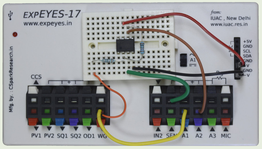
Wiring Diagram
Photograph of the experimental
setup. Used OP07 (pin
configuration of uA741)
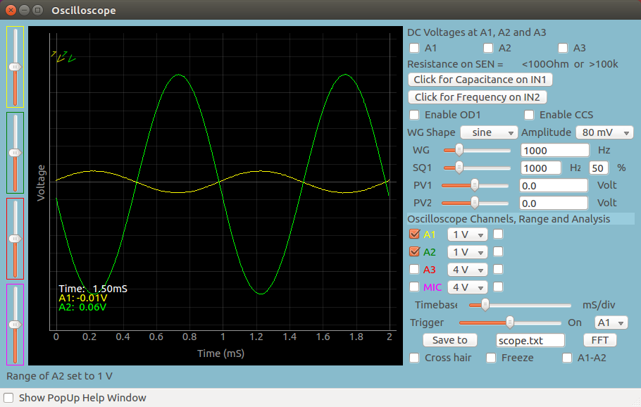
Screen shot of the oscilloscope program showing inputs and output of
an Inverting Amplifier. Gain is -10
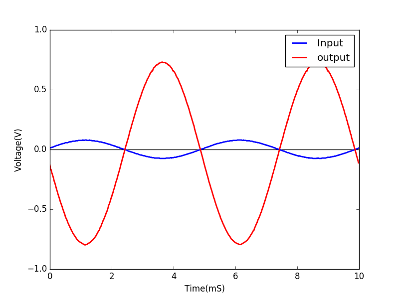
Writing Python Code
This experiment can also be done by running this Python
Code. The output of the program is shown
below.
importeyes17.eyesp=eyes17.eyes.open()frompylabimport \*p.set_sine(200)p.set_pv1(1.35)# will clip at 1.35 + diode dropt,v,tt,vv=p.capture2(500,20)# captures A1 and A2xlabel('Time(mS)')ylabel('Voltage(V)')plot([0,10],[0,0],'black')ylim([-4,4])plot(t,v,linewidth=2,color='blue')plot(tt,vv,linewidth=2,color='red')show()