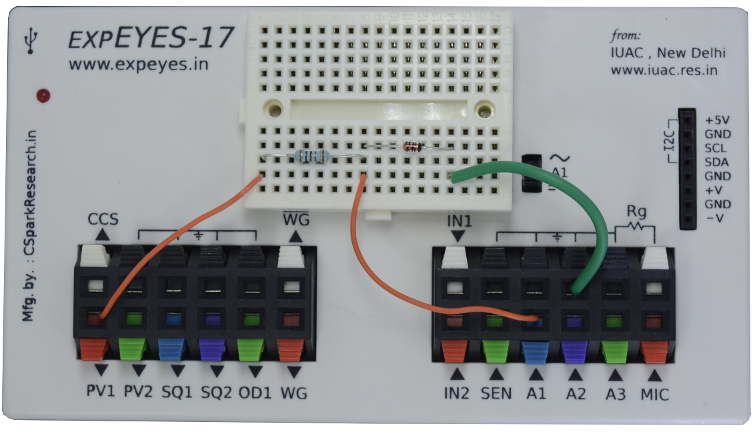
The schematic is wired as shown in the diagram below. The voltage across the diode is measured on A1. The anode of the diode is connected to PV1, through a 1k resistor. Voltage at PV1 is incremented in steps and at each point the voltage across the diode is measured. The current is calculated from $ i = \frac{PV_1-A_1}{R} $. The diode used is 1N4148, silicon diode.
 |
|
| Wiring Diagram | Photograph of the experimental setup. |
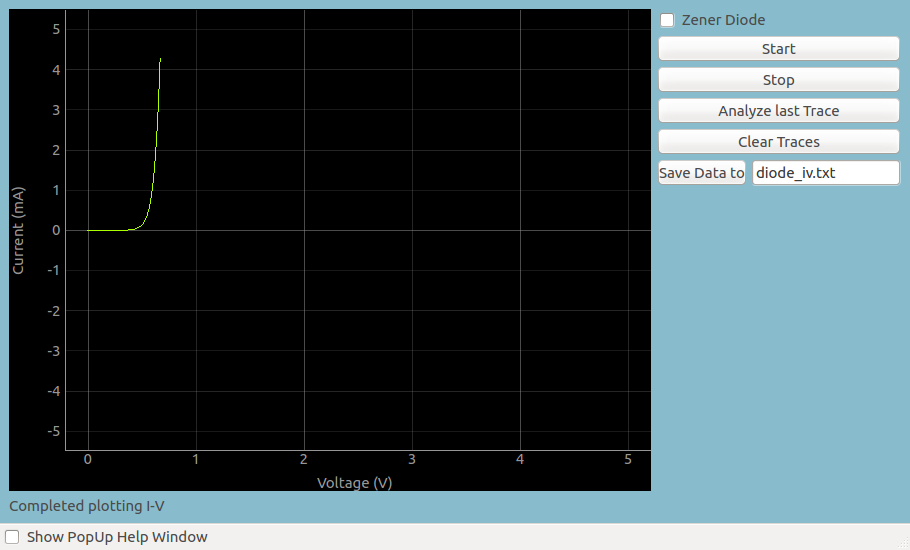 |
| Screen shot of Diode IV characteristic |