In this section, we explore the transient response of a series RC circuit by applying voltage step and capturing the voltage variation across the capacitor.
 |
|
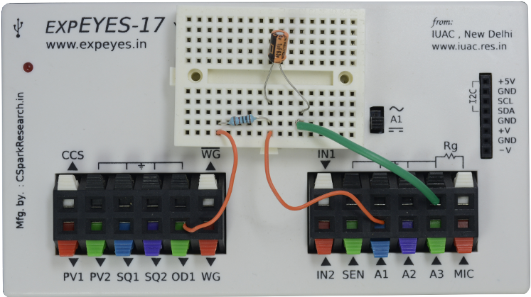
| Wiring Diagram | Photograph of the experimental setup. |
The voltage steps are generated on OD1 by clicking on the buttons on the GUI. The observed waveforms are shown below, showing the voltage variation across a capacitor while charging and discharging through a resistor.
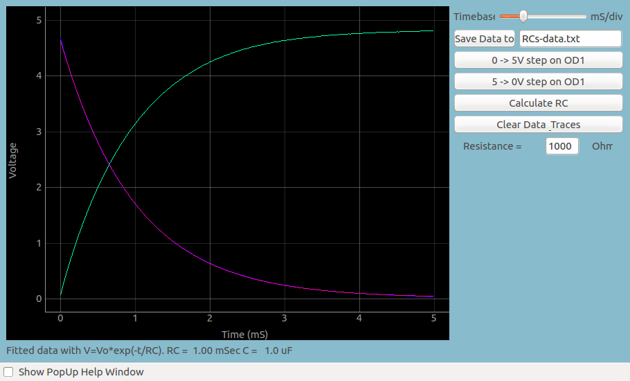 |
| Screen shot of the voltage across a capacitor during charging and discharging |